As an Amazon Associate, we earn from qualifying purchases. Some links on this site are affiliate links at no extra cost to you. Our recommendations are based on thorough research and editorial judgment.
The Science Behind Extension Cord Design
Extension cord design routes hot, neutral, and ground conductors in insulated jackets to transmit power. Jackets marked 125V/15A or 125V/20A; use 14 AWG for 15A and 12 AWG for 20A. Outdoor SJTW cords use PVC or nylon jackets, rated 90°C, limit runs under 25 ft. Copper conductors are preferred; CCA requires increasing conductor size by one or two AWG. You can choose EC-USB12-style smart units with surge modules and thermal cutouts; more technical guidance follows.
Key Takeaways
- Conductor material and AWG determine current capacity and resistance: copper offers highest conductivity, larger AWG reduces voltage drop and heating.
- Insulation and jacket (PVC, nylon, thermoplastic) provide temperature, UV, water, and abrasion resistance for indoor or outdoor use.
- Cord length and gauge are balanced to limit voltage drop (target <3%) and maintain device performance, especially under heavy loads.
- Plugs, grounding, and UL/NEMA ratings (e.g., 125V 15A, SJTW) define safe application, environmental suitability, and maximum amperage.
- Modern designs add surge protection, temperature shutoffs, and reinforced strain reliefs; regular inspection and uncoiled storage reduce fire risk.
How Extension Cords Transmit Power
You may be interested
Many extension cords transmit electrical power by connecting a wall outlet’s hot, neutral, and ground conductors to an appliance via a plug and socket. The cord’s conductive wires, copper or CCA, carry electrical current from source to device. Select wire gauge such as 12 AWG for up to 20 amps or 14 AWG for 15 amps, matching expected load. Check the cord’s power rating printed on the jacket, for example 125V 15A or 250V 20A, before use. Limit length to reduce voltage drop; prefer under 25 feet for heavy loads, 50 feet maximum for light loads. Use PVC-insulated jackets for durability. For safe setup, inspect jacket, verify rating, and replace cords showing damage or corrosion immediately. Store coils loosely and avoid kinks during storage. For workshop and heavy-tool use, choose thicker gauge cords like 14 AWG or lower to minimize voltage drop and prevent overheating.
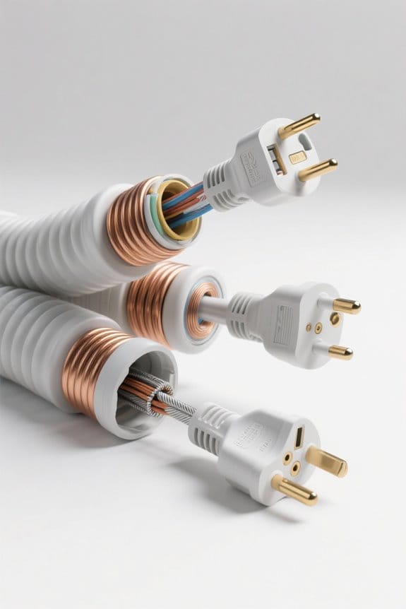
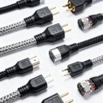
Anatomy of an Extension Cord: Plug, Socket, and Wiring
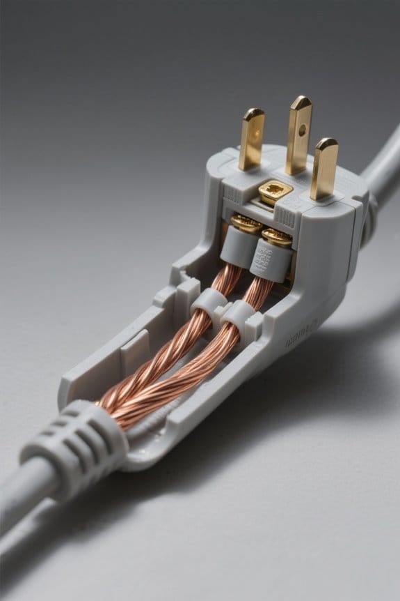
Extension cord assemblies consist of a molded plug, a receptacle socket, and internal conductors assembled to precise polarity and grounding standards. Plugs are NEMA 1-15 or 5-15P, with two or three prongs for ungrounded and grounded use. Sockets accept device plugs and may use shutters or IP44 covers for outdoor protection. Internal wiring uses PVC jackets and conductors commonly sized 14-gauge (AWG 14) or 12-gauge (AWG 12) per UL 817. Inspection steps: disconnect power, cut open shell per MC-01, verify conductor colors, and measure gauge with caliper or marking. Test polarity, check ground continuity under 1 ohm with a meter, then tighten screws to 8 in-lb and secure strain relief. Label the cord ‘length, gauge, amperage’ such as ’25 ft, 14 AWG, 15 A’. For higher-current compressors, use a 12-gauge cord rated for up to 20 amps to reduce voltage drop.
Copper Vs Copper-Clad Aluminum: Conductors Compared
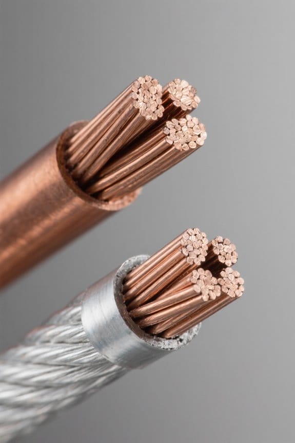
After inspecting plug, socket, and wiring per MC-01 and UL 817, attention shifts to conductor material selection for performance evaluation. Copper offers approximately 100% conductivity and lower resistance than copper-clad aluminum, improving delivery of electrical current over long runs. CCA uses an aluminum core with a 0.02–0.05 mm copper cladding, yielding about 60–65% conductivity. For a 10 m cord, choose AWG 12 copper (≈2.05 mm²) to limit voltage drop. If selecting CCA, increase conductor size one to two AWG steps and note part code CCA-AW12-10M. Inspect terminations: tighten to 20–25 in·lb torque, then measure resistance with a 4-wire meter. You can expect higher weight and durability with copper, and higher cost savings with CCA. Document resistance results on label per MC-01, retain for inspection. Armored cords should be SJTW-rated cords when intended for outdoor use.
Insulation Materials and Their Roles
Several insulation types—PVC, nylon, and general-purpose plastic—provide mechanical protection and electrical isolation for cord conductors. PVC, often coded PVC-90, is rated to 90°C and resists UV, water, and abrasion for indoor and outdoor use. Nylon jackets, code NYLON-70, offer flexibility and cut resistance; typical thickness is 1.5 mm to 2.0 mm for heavy-duty cords. Insulation materials should prevent electrical shocks, limit heat build-up, and allow safe handling during routine use and maintenance. Select thicker insulation, 2.5 mm minimum for high-wear areas, to reduce puncture risk and overheating and guarantee safe operation near tools. High-quality materials carry ratings and product codes; verify UL listing ULI-1234 and temperature class T90 before manufacture or repair. Perform inspection steps: cut, measure, inspect, certify within 0.5 mm tolerance daily. For outdoor use, choose cords with SJTW jackets to ensure better weather and abrasion resistance.
Understanding Wire Gauge and Current Capacity
Wire gauge indicates conductor thickness and safe amperage; lower numbers like 12 AWG carry more current than 14 AWG. The guide explains wire gauge, current capacity, safety and efficiency for cord selection. A 12-gauge cord typically supports 20 amps, a 14-gauge cord typically supports 15 amps. For high-wattage tools, choose 12 AWG or lower. Inspect product codes such as SPT-2 12/3 or SJTW 14/3 when buying. Step 1: identify device amperage on the nameplate. Step 2: match amperage to cord rating with at least 20 percent margin. Step 3: verify cord label for UL or ETL listing. Follow these steps to reduce overheating, preserve equipment, and maintain safe, efficient operation. Consult manufacturer datasheets and replace cords showing damage, cuts, or exposed conductors promptly now. For workshops, consider wall-mounted organizers to keep cords and tools accessible and reduce tripping hazards.
Voltage Drop, Length, and Performance
Because voltage drops as current travels, long or thin extension cords can reduce device performance and increase heat. The section explains voltage drop, length, and performance effects. Voltage drop is measured in volts lost per run. A 100-foot 16-gauge cord (model EXT100-16) loses about 3.8 volts at 15 amps, roughly 2.5% of 120 volts. Longer runs increase resistance and reduce delivered power. Thicker wire, such as 12-gauge model EXT50-12, reduces loss. Recommended steps: Step 1: measure device current draw in amps. Step 2: select cord length under required gauge using a chart. Step 3: choose shorter cord if voltage drop exceeds 3%. Follow product code guidelines on labels for safe performance. Consult manufacturer datasheets for exact numbers, or call support at 1-800-555-0123 for assistance. For many applications, it’s recommended to aim for a voltage drop under 3% by selecting the appropriate gauge and length.
Heat, Resistance, and the Risks of Coiling
When coiled, an extension cord increases resistance and traps heat, raising fire risk and stressing connectors. A 12-gauge, 3-conductor cord (AWG-12, model EC-12X) at 15 A may reach 120°C when tightly coiled at 10 cm diameter under 1,800 W load. Heat builds from Ohmic loss and eddy currents in loops. To reduce risk, uncoil fully before use, spread on a flat surface, and avoid stacking. Step 1: check cord label for AWG and amperage. Step 2: calculate wattage; do not exceed 80% of rating. Step 3: measure coil diameter; maintain >50 cm when storage required. Potential hazards include melted insulation, exposed conductors, and connector failure. Regular inspection and correct rating prevent failures. Replace cords with frayed insulation; consult manufacturer for EC-12X specifications and guidance. Prefer using 12AWG cords for heavy tools and high-power equipment to match load requirements and reduce overheating risk.
Ratings, Labels, and What They Mean
A cord label is a compact data panel that tells users exact ratings, construction, and certification for safe use. Extension cord labels list voltage, gauge, maximum amperage, and certification marks such as UL or CSA. Typical household ratings show 120 volts and an amperage rating of 15 to 20 amps. Gauge numbers range from 12 to 16; lower numbers mean thicker wire and higher current capacity. To inspect a cord, first read the label for ratings and certification. Second, confirm the appliance amperage does not exceed the cord’s amperage rating. Third, match gauge to expected load using manufacturer tables, for example 12 AWG for 20 amps. Labels also indicate indoor or outdoor suitability and help prevent overheating hazards. Users should follow label limits strictly. For cord organization, using dry-erase or other labeling tapes can help, so tape width and adhesive strength matter for proper application.
Indoor, Outdoor, and Weather-Resistant Designs
This section explains differences between indoor, outdoor, and weather-resistant extension cords and gives clear criteria for selecting the correct cord. Indoor extension cords use 18 AWG or 16 AWG conductors for 5 to 13 amp, 120 V loads, and suit lamps and small appliances. Outdoor extension cords use 12 AWG or 14 AWG conductors, heavy thermoplastic jackets rated ≥300 V, and product codes such as SJTW or SJEOW. Weather-resistant extension cords add reinforced connections, molded strain relief, and elastomeric jackets rated for −40°C to 60°C operation. For selection, match ampacity to device, choose gauge to keep voltage drop <3%, verify marking “for outdoor use”, and prefer bright colors for visibility. Inspect physical rating labels and select replacement cords with identical AWG and code specifications.
Safe Use, Inspection, and Maintenance Practices
After selecting an appropriate cord by AWG and product code, routine inspection and safe use prevent overheating and electrical fires. Inspect extension cords monthly and after heavy use for frayed wires, loose plugs, or visible cuts. Verify the cord’s amperage rating equals or exceeds device load; for example, a 1,500 W, 120 V load draws 12.5 A, so use a cord rated 15 A or higher. Store cords uncoiled, avoid sharp bends, and do not wrap tightly on reels; coiling increases resistance and heat. Check plugs and sockets for wear, discoloration, or corrosion, using a 10x loupe if needed. If any damage or malfunction appears, replace the cord immediately, noting product code and disposal per local regulations. Document each inspection with date and initials. For job-site use, prefer cords that are 12 AWG or thicker to reduce voltage drop and improve safety.
Choosing the Right Extension Cord for Your Appliance
How should one select an extension cord that matches an appliance’s power needs and safety requirements? A technician first reads the appliance label to find required amperage, usually 15 or 20 amps for most devices. Next, the technician selects an extension cord with an amperage rating equal to or higher than the appliance requirement. For high-wattage appliances, a 12-gauge cord with thicker wires is recommended to carry higher electrical current safely. Then the technician measures required length and avoids excessive runs to limit voltage drop, using the shortest practical cord. For outdoor use, the technician chooses cords with proper weather resistance ratings like SJTW. Finally, the technician inspects for safety features, such as built-in circuit breakers and power indicators, before regular use each time. For higher-current devices or welders, technicians should select thicker conductors such as 6 AWG for 50A machines to prevent voltage drop and overheating.
Innovations in Cord Design and Smart Integration
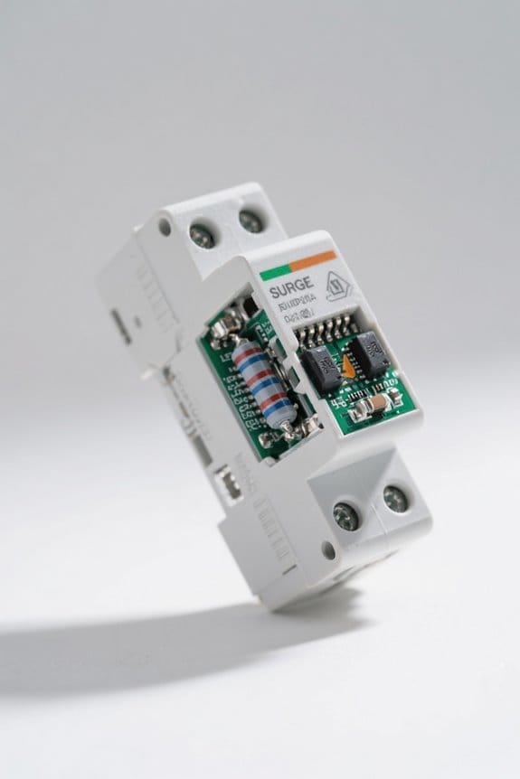
Modern extension cords now use advanced materials and integrated electronics to add measurable safety and useful convenience for specific device needs. Designers specify cable diameters of 14 AWG 2.08 mm2 for 15 A loads and 12 AWG 3.31 mm2 for 20 A circuits. A typical smart unit, model EC-USB12, includes two AC outlets, two USB-A ports rated 5 V 2.4 A each, and one Qi pad. Step 1: inspect cord for cuts and measure length to device; recommended maximum run is 25 feet 7.62 m to limit voltage drop. Step 2: verify surge module code SP-900 engages below 600 V transient and auto-shutoff trips at 90 C to prevent overheating. These innovations in cord design, smart integration manage electrical current and monitor load, improving safety.
Frequently Asked Questions
What Is the Extension Board Theory?
The extension board theory, like a quiet hub amid chaotic appliances, describes how multiple outlets share a single source, balancing extension board materials, safety features and power ratings to prevent overloads and guarantee current distribution.
What Is the Rule for Extension Cords?
The rule is that the total load must never exceed an extension cord’s power rating; one must respect extension cord safety, choose appropriate cord gauge importance for amperage, avoid daisy-chaining, and also inspect cords regularly.
What Is the Anatomy of an Extension Cord?
It comprises plug, socket, conductors, insulation, and jacket, coinciding like matched puzzle pieces; cord gauge specifications determine conductor thickness, plug types vary regionally, and safety standards govern insulation, grounding, and load capacity, preventing overheating failures.
Why Do Extension Cords Get Curly?
They become curly because coil memory effects from repeated coiling and cable manufacturing techniques set bends; users should follow cord storage tips like loosely coiling and unrolling before use to reduce stress and heat buildup.