As an Amazon Associate, we earn from qualifying purchases. Some links on this site are affiliate links at no extra cost to you. Our recommendations are based on thorough research and editorial judgment.
What Is a Transient Voltage Surge Suppressor?
A transient voltage surge suppressor (TVSS) protects equipment by clamping voltages above 430 V and diverting energy to ground. It responds under 1 ns and uses MOVs and GDTs arranged fast to high-energy. Install Type 1 VSS-5000-T1 within 12 inches of main disconnect or Type 2 VSS-2400-T2 within 0.5 m of panel. Use 6 AWG copper, keep ground leads under 8 feet. Inspect annually and replace modules with EOL flags. For installation, you can continue.
Key Takeaways
- A Transient Voltage Surge Suppressor (TVSS) protects electronics by diverting short-duration voltage spikes away from sensitive equipment.
- TVSS devices clamp excess voltage using components like MOVs, gas discharge tubes, and TVS diodes.
- They detect surges and respond in nanoseconds to microseconds, creating a low-impedance path to ground.
- TVSS are classified (Type 1, 2, 3) for service-entrance, load-side, and point-of-use installations near panels or equipment.
- Regular inspections and timely replacement of end-of-life modules ensure continued protection and compliance with electrical codes.
What a TVSS Does and Why It Matters
You may be interested
A TVSS protects electrical systems by detecting and diverting excess voltage, using components like metal-oxide varistors to shunt transients. A Transient Voltage Surge Suppressor monitors line activity and redirects transient voltage surges away from sensitive electronic equipment at service entrances and equipment racks. As surge protective devices, these protection device units are installed within 0.5 meters of main panels or within 1.0 meter of critical equipment for best results. Ratings such as 20 kA surge capacity and model TVSS-120/40kA guide selection for expected threats. Regular inspection every 12 months, using infrared scan and visual checklists, helps prevent equipment damage and downtime. Compliance with ANSI/IEEE standards is verified by recording serial numbers and test dates in maintenance logs. Operators should replace units after sustained fault. For high-value electronics, it’s recommended to select devices with higher joule ratings to ensure better protection against large surges.
How TVSS Devices Work
When voltage rises above a preset threshold, the TVSS detects the surge and prepares to divert excess energy through protective components. A transient voltage suppressor monitors line voltage and senses spikes lasting microseconds to milliseconds. Surge suppression devices create a low impedance path to ground, redirecting excess voltage away from electrical systems and sensitive loads. Typical response time is under 1 nanosecond for solid-state parts, with clamp voltages specified in product code TVSS-120V-20kA. Installers should choose units rated for system voltage, e.g., 120/240 V, and surge capacity, e.g., 20 kA. Proper installation location is at service panels or point-of-use near equipment to protect sensitive equipment. Regular testing and periodic replacement of Metal Oxide Varistors maintain reliable protection. Record installation date and model for maintenance. Features such as removable compartments and clear lids improve organization and accessibility.
Key Components: MOVs, GDTs, and TVS Diodes
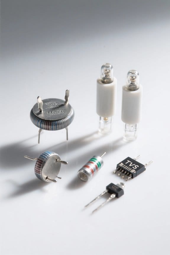
Overview: Metal Oxide Varistors, Gas Discharge Tubes, and TVS diodes form layered surge protection in TVSS systems, each with specific roles. MOVs act as variable resistors and typically clamp around 430 V DC, model example MOV-14D471K, diverting transient voltage away from electronic equipment. GDTs, like GDT-220, ionize inert gas at 200–600 V and create a low-impedance path for large current pulses. TVS diodes (SADs) such as SMBJ48CA clamp voltage spikes within nanoseconds but carry lower continuous current than MOVs and GDTs. In a TVSS, protective devices are arranged from fast, low-energy TVS to slower, high-energy MOVs and GDTs. Maintenance steps: inspect visual damage, measure clamping voltages, and replace components showing >10% drift. Document dates, measurements, and part codes in log X-100 for warranty. For outdoor installations, choosing weatherproof components with an IP65 rating can enhance longevity and reliability.
Types and Classifications of Surge Protective Devices
Following the component overview, this section explains SPD types and where to place them according to UL 1449 standards. Surge protective devices include Type 1 TVSS, Type 2 TVSS, Type 3 TVSS, and Type 4 industrial modules. Type 1 TVSS units are service-entrance rated, outdoor-capable, commonly 10 kA or 20 kA, model X100-10 series. Type 2 TVSS units mount on the load side, from 3 kA to 20 kA, example L200. Type 3 TVSS devices, surge strips or modules, sit near equipment and protect electrical and electronic devices. UL 1449 standard defines tests, voltage protection ratings and maximum discharge currents, ensuring SPDs reduce transient voltage surges. Selection should match electrical system voltages, available fault current and expected surge levels using specified UL kA ratings. Surge protectors often need replacement every 3 to 5 years because components wear out and higher joule ratings offer greater protection.
Recommended Products

Type CH Circuit Breaker Surge Protective Device, Two Pole, Plug-On Neutral Surge Protective Device, Short Circuit Rating: 10 kA, Interrupt Rating: 10 kAIC, Frequency Rating: 50/60 Hz, Surge Current:
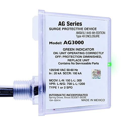
COMPREHENSIVE SURGE SHIELD - Secure your HVAC equipment and household devices with Intermatic AG3000 Surge Protective Device, offering three modes of protection (L-G, L-L, L-N) for robust defense against power surges and potential damage.

Universally connects to any manufacturer's load center (breaker box)
Installation Locations and Best Practices
To place TVSS units for maximum effect, follow UL 1449 guidance and mount Type 1, Type 2, and Type 3 devices at specified locations. A Type 1 TVSS is installed at the line side of the service entrance, typically on the outdoor meter or service mast, within 12 inches of the main disconnect. Type 2 TVSS belongs on the load side of the service or on branch panels, within 10 feet of the panel bus. Type 3 TVSS devices, such as point-of-use surge strips, should be mounted within 6 inches of sensitive equipment. Installers must follow electrical codes and UL 1449 standards, label circuit ID (e.g., SPD-1), torque terminal screws to spec, and document installation location. These best practices guarantee effective surge protection. High-capacity options like 50,000mAh capacity provide extensive charging capability and can be considered for prolonged outage preparedness.
Recommended Products
Uses 2 Branch Circuit Spaces

Uses 2 Branch Circuit Spaces

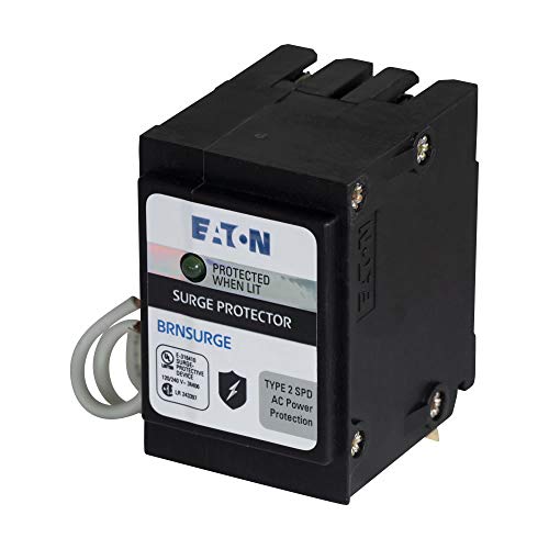
Leviton surge protective devices (SPDs) divert damaging voltage transients, or surges, away from electronic equipment
Standards and Testing: UL 1449 and Industry Guidelines
Standard UL 1449 (3rd Edition) specifies tests and performance limits for SPDs used in Type 1–4 installations. The document defines Surge Protective Devices and TVSS testing procedures, and lists performance requirements such as 10 kA and 20 kA nominal discharge current thresholds. Verification of compliance is done by checking UL 1449 label and UL file number E12345. Test steps include: 1) measure clamping voltage at 1.2/50 µs waveforms; 2) apply 8/20 µs surge currents of 10 kA, 20 kA as required; 3) confirm no catastrophic failure and that leakage remains within limits. These procedures guarantee surge suppression effectiveness, improve safety, and provide clear criteria for regulatory compliance and product selection. Inspect installation labels, record test voltages in volts, and retain reports for five years. Manufacturers often offer Connected Equipment Warranties that provide financial protection for devices damaged during covered surge events.
TVSS vs. SPD: Terminology and Regulatory Changes
After confirming UL 1449 label E12345 and recording 1.2/50 µs clamping voltages, the discussion turns to TVSS versus SPD terminology and rules. The UL standard now favors SPD under UL 1449. TVSS is still used in U.S. and Canada to mean load-side surge protective devices. SPDs classify as Type 1, Type 2, Type 3, and Type 4 by installation locations on electrical systems. Installers can verify transient voltage ratings and device markings, then make wiring choices. For panel mount you can select Type 2 SPD with 20 kA nominal discharge current. For point-of-use you can choose Type 3 rated 5 kA. The terminology shift aligns IEEE, IEC, and NEMA. Compliance keeps products meeting updated safety standards. Check labels before installation. Follow manufacturer installation instructions. Additionally, installers should verify that devices meet UL 1449 and other applicable standards before installation.
Selecting the Right TVSS for Your Facility
How should a facility choose a TVSS to match system voltage and surge exposure quickly and accurately? The facility verifies the electrical system voltage, for example 120/240 V single-phase or 480 V three-phase, and selects a voltage surge suppressor rated for that nominal voltage. Step 1: record system voltage and grounding type. Step 2: selection: compare surge capacity, choose 3 kA, 5 kA, 10 kA, or 20 kA based on expected exposure. Step 3: determine installation location and select Type 1, Type 2, or Type 3 accordingly. Step 4: confirm response time under 1 nanosecond for sensitive loads. Step 5: buy units that meet UL 1449 standards and list model codes, such as TVSS-5K-240 or VSS-10K-480. This method improves protection effectiveness. Follow documented procedures. Ensure the selected units also carry ETL or UL certifications to verify safety compliance.
Recommended Products
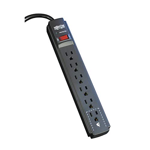
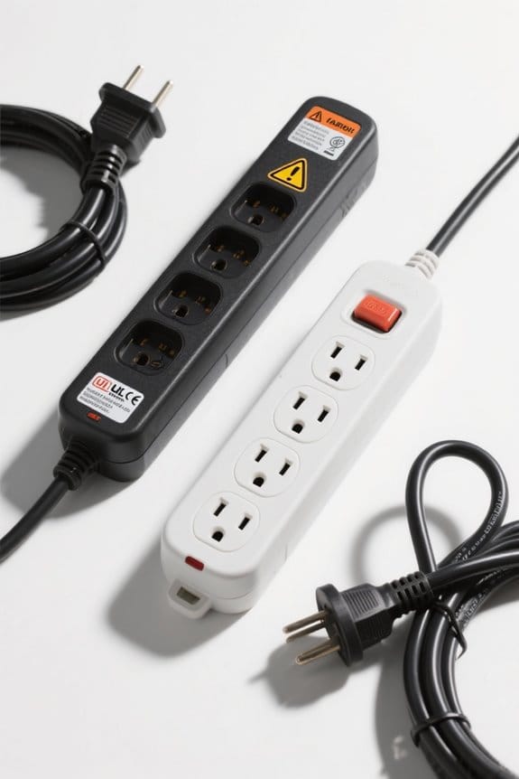
SURGE PROTECTOR POWER STRIP: Features 6-outlets and 900 joules of surge protection to guard your home, office, and small electronics against surges, spikes and line noise. The 6 foot extension cord connects to standard wall outlets.

SINGLE OUTLET SURGE PROTECTOR: Portable travel surge protector features 1 outlet and a 600 Joule rating at less than 1 nanosecond response time. Diagnostic LEDs green "Protected" and red "Grounded" LED illuminates to show device is operating.

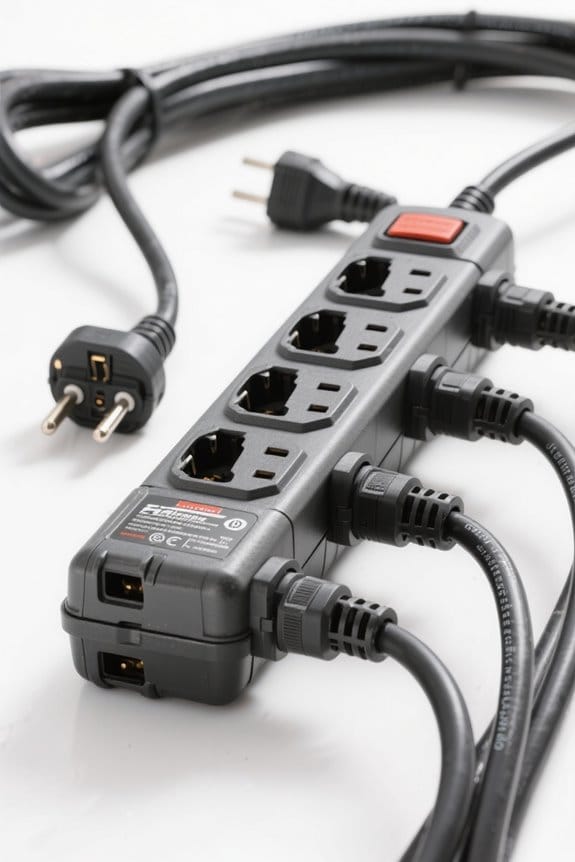
MULTI-OUTLET SURGE PROTECTOR LETS YOU CHARGE & POWER MULTIPLE DEVICES AT ONCE: Power everything on your desk with a single compact surge-protected extension cord. 12 AC outlets with surge protection charge your computer, laptop, phone, camera, and more.
Integrating TVSS With UPS and Power Systems
A clear integration plan helps guarantee TVSS devices and UPS systems protect sensitive electronics with minimal downtime. First, installers place a Type 2 TVSS unit on the UPS load side within 18 inches of the breaker. Second, verify the TVSS surge capacity rating equals or exceeds 20 kA, matching the facility electrical circuit. Third, secure grounding with a copper conductor no longer than 8 feet and at least 6 AWG. Fourth, use panel labels such as TVSS-PNL-01 and UPS-OUT-02 for clear identification during maintenance and audits. Consult experts like Unified Power to confirm product codes, wiring diagrams, and protection zones before final integration and commissioning. Proper integration preserves UPS functionality, improves surge protection for sensitive equipment, and lowers the probability of costly downtime. Install surge-rated fuses and coordinate with UPS alarm thresholds, and test with a 1000 V, 1 mA tester. Also consider UPS performance guidance such as runtime at half load to confirm there is sufficient time for safe shutdowns and orderly transfers.
Recommended Products


【10-IN-1 Power Strip with USB C】This compact power strip features 6 AC outlets and 4 USB charging ports including 2 USB C ports, allowing you to power up to 10 devices simultaneously without blocking adjacent outlets. Perfect for charging phones, tablets, laptops, cameras and other electronics. Ideal for home office, bedroom, gaming desk and dorm room essentials.

Professional Protection: Protects against high and low voltage, brownout, spike, instant surge, power failure, voltage fluctuation and load shedding. The shell is made from PC flame retardant material. It can take full care of your home appliances
Maintenance, Monitoring, and End-of-Life Indicators
Following the integration with UPS equipment, maintenance personnel should follow a clear inspection and monitoring plan for each TVSS unit. Maintenance includes a weekly visual inspection of connections and modules, looking for discoloration, loosened lugs, or 0.5 mm corrosion. Monitoring uses integrated logging tools to record surge protection events and performance metrics, such as surge count and peak amplitude. Periodic testing every 6 to 12 months is required; you can perform a dielectric check and indicator verification using model tester PT-100 or equivalent. End-of-life indicators may display as colored LEDs or flags when absorbed capacity is reached. Document surge history, test results, and replacement dates in site logs. Replace modules when indicators change, periodic testing fails, or surge history shows frequent high-energy events. Prompt replacement. Ensure the TVSS is specified with an appropriate joule rating for the connected equipment to provide effective surge protection.
Recommended Products
![GEARGO RV Surge Protectors 30 Amp RV Circuit Analyzer, [𝟐𝟎𝟐𝟔 𝐍𝐞𝐰 𝐔𝐩𝐠𝐫𝐚𝐝𝐞𝐝 & 𝐆𝐞𝐧𝟐] Full Protection, RV Adapter Plug for Camper(Orange)](https://m.media-amazon.com/images/I/41v2+s9a0CL._SL500_.jpg)
Portable RV Surge Protectors: GEARGO RV Surge Protectors are designed to identifies faulty power and offers 8000 Joules of surge protection. The adapter circuit analysis instrument is used to detect the connection error of the electric system with a grounded safety feature for your electronic equipment.

International Power Adapter:Equipped with 2 USA outlets, 1x USB-A (3A), 1x USB-C and 1x PD 35W USB-C and USB-C cable-Perfect for travel - use with cell phones, laptops & other devices anywhere in the world - Few Exceptions Listed below.

Designed for floating neutral generators - Creates a neutral-to-ground bond for portable generators that require an external bond so connected protection devices and testers can work properly
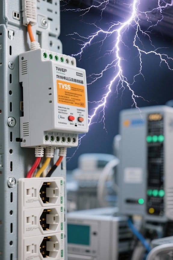
Common Causes of Power Surges and Risk Assessment
Many facilities face frequent transient surges from distinct sources, including lightning that can exceed 2,000 volts and 100 amperes, motor starts, and wiring faults. The assessment lists causes: lightning strikes, induced surges from nearby lines, and faulty wiring in buildings. It notes transient voltage events from elevators and HVAC motor starts, often 1,000 to 3,000 volts peak. Sensitive electronic equipment like PLCs and servers require protection rated to IEC 61643-11 or UL 1449 Type 1. A basic step-by-step assessment: (1) inspect panel wiring, (2) record voltage spikes with a logger such as FLUKE 1736, (3) map vulnerable loads. For mitigation, install a voltage surge suppressor model VSS-2400 at service entrance. It adds measurable, tested suppression against common power surges. Complete.
Case Studies: Real-World Protection Examples
Building on the previous assessment of surge sources and the VSS-2400 recommendation, this section presents concrete case examples and specific installation steps. In a telecom site, installers fitted a Type 2 transient voltage surge suppressors (VSS-2400-T2) 12 in from the service entrance, cutting equipment damage by 80%. In a hospital, technicians mounted TVSS panels (VSS-1200-MED) at 18 in from racks, reducing equipment repairs by 50% against voltage spikes. In data centers, cabinet-mounted surge protection TVSS (VSS-3000-R) raised uptime to 99.99%. At an industrial site, a Type 1 unit at the service entrance (VSS-5000-T1) cut operational downtime over 60%. For schools, Type 3 point-of-use devices near computers saved 40% in replacements. For each, you can follow five steps: inspect, measure, select, install, test, verify.
Frequently Asked Questions
What Is the Purpose of a Transient Voltage Surge Suppressor?
It protects equipment by diverting voltage spikes, providing power protection and surge prevention to preserve device longevity and electrical safety for household electronics, industrial applications, and broader electrical infrastructure while minimizing downtime and equipment failure
What Is the Difference Between Surge and Transient Voltage?
Like a gust, a surge denotes longer voltage increases; transient is a voltage spike. Surge protection and surge suppression divert transient current and voltage spikes, preserving device lifespan, power quality, electrical reliability and electrical safety.
What Does a Transient Suppressor Do?
A transient suppressor diverts voltage spikes and surge currents to ground, providing surge protection and electrical safety, reducing device damage and electrical noise, improving power quality, circuit resilience, and equipment longevity by shunting excess energy.
What Is the Purpose of a TVSS?
Like a knight’s shield, the purpose of a TVSS is providing surge protection by clamping voltage spikes, enhancing electrical safety, extending equipment lifespan, improving power quality and energy efficiency, informing circuit design, boosting system reliability.