As an Amazon Associate, we earn from qualifying purchases. Some links on this site are affiliate links at no extra cost to you. Our recommendations are based on thorough research and editorial judgment.
How Utility Extension Items Have Changed Over Time
Utility extension methods moved from makeshift 4×4 supports to treated poles and sensor systems. Early fixes used 4×4 posts buried 36 inches, attached with GB12-34 U-bolts, and 45-gallon concrete-filled barrels for weight. Modern poles are treated, often 40 ft with 10 in base, inspected every 5 years, and coated with ROT-GUARD™, BG-100 or TG-45 per code. Recoil cords like RC-500 retract 1.2 m to 7.6 m. GIS EPSG:4326 tags track locations, and further specifics follow.
Key Takeaways
- Temporary makeshift supports evolved into engineered pole treatments and standardized anchoring following NESC and ANSI guidelines.
- Wooden poles moved from simple untreated wood to pressure-treated, preservative-coded poles with 30+ year lifespans.
- Specialized protective coatings (ROT-GUARD™, BLAZE-GUARD™, TERMI-GUARD™) replaced ad-hoc sealing to proactively prevent decay, fire, and pests.
- Extension accessories like recoil cords advanced from spring reels to polymer reels with locking mechanisms and remote monitoring.
- Maintenance shifted from informal DIY fixes to GIS-tracked inspections, ISO/IEC testing, and five-year regulatory retesting cycles.
Early Practices: Makeshift Supports and Temporary Fixes
You may be interested

When utility poles showed rot or lean, property owners often installed temporary support systems using standard fence posts and straps. They used 4×4 treated posts, 36 inches buried, attached with 1/2-inch galvanized U-bolts GB12-34. Concrete-filled 45-gallon barrels added weight, typically 300 pounds each, placed 6 inches from the pole base. Metal stays bolted to nearby structures used 3/8-inch hex bolts, torque to 25 ft-lbs, aligning supports at forty-five degrees. DIY repairs aimed to preserve service and power supply, reducing immediate cost while scheduling professional replacement within six months. A recommended step-by-step is: excavate 12 inches, set post, pour 80 lb. concrete bag, strap post, check level. Safety note: avoid live conductor contact, de-energize circuits when possible, call utility if work nears primary conductors. For temporary power tools used during these fixes, always use a heavy-duty 12-gauge cord to minimize voltage drop and overheating.
The Rise of Centralized Power and Utility Expansion
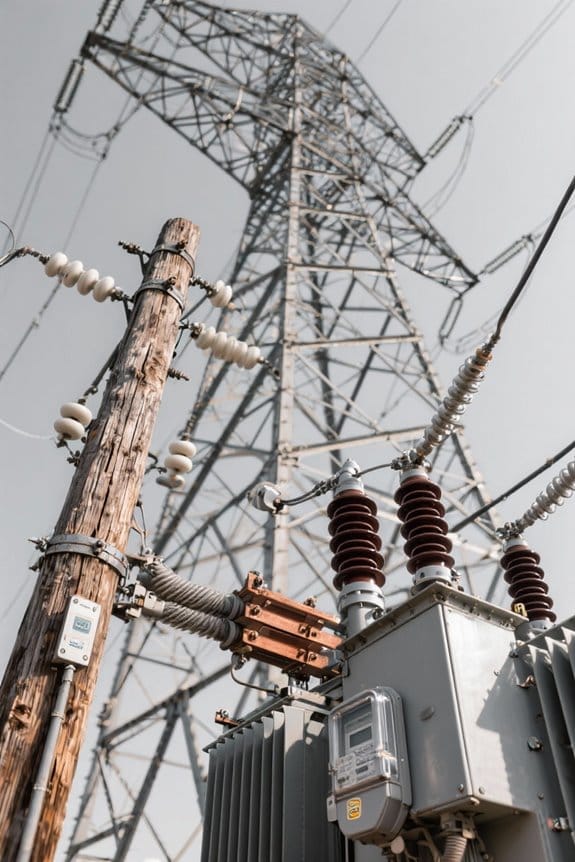
The late 19th century marked the start of centralized electric power with Edison’s Pearl Street station in New York City, 1882. Centralized generation led to factory shifts from steam to electric motors, increasing output by 30 percent. Reliance on coal and natural gas shaped transmission expansion, adding 138 kV lines and standard 12.7 m crossarms on poles. The 1970s energy crisis prompted audits, and utilities adopted efficiency measures following three steps: assess, retrofit, diversify. For field crews, step one instructs measuring span lengths with a 30 m tape, note code UE-1970. Step two directs retrofitting transformers to 500 kVA units, model TX-500, and verify insulation resistance at 1,000 MΩ. Step three requires installing smart grid meters, model SG-100, logging results to 16GB USB drive. For field operations, crews should also prioritize using 12 AWG or thicker extension cords on-site to reduce voltage drop and enhance safety.
From Wood to Treated Poles: Advances in Pole Preservation
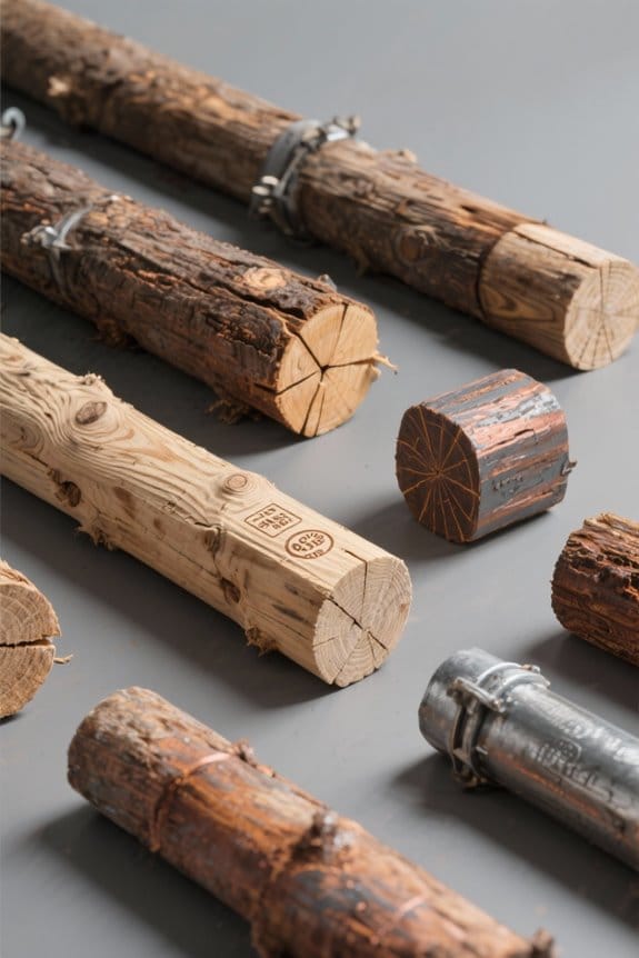
Pole longevity is now measured in decades rather than years, as treated poles resist decay and insect damage for more than 30 years. The industry moved from untreated timber to poles preserved with advanced materials and chemical preservatives. Typical pole size 40 ft by 10 in base, 6 in top receives 3-step treatment: clean, pressure-impregnate, air-dry. Use preservative code CP-204 or CA-310 as examples. Inspect poles every 5 years at 0–6 ft groundline for rot and 6 in intervals along length. Replace or re-treat when decay exceeds 25% cross-section loss. Installation follows NESC Section 3, set depth one-tenth pole length plus 2 ft. Field crews record treatment date, inspector ID, GPS coords. Additionally, crews commonly use armored extension cords and GFCI-protected equipment during treatment and inspection to ensure electrical safety.
Specialized Protection Products: ROT-GUARD™, BLAZE-GUARD™, TERMI-GUARD
ROT-GUARD™ resists fungal decay and extends service life, backed by 25-year independent test data and field trials. It provides extensive rot protection for utility poles in wet, dry, and coastal environments zones. BLAZE-GUARD™ (code BG-100) creates a flame barrier reducing heat transfer by 60% at 800°C exposure during 30-minute tests. TERMI-GUARD™ (code TG-45) repels and eliminates termites when applied at 2.0 kg per pole in a 3-step coating process. Independent laboratory and field data validate performance over decades and support environmental sustainability claims under protocol ES-7. Technicians follow three steps: clean to 0.5 mm surface roughness, apply specified dose, then inspect after 30 days. Adoption of these products signals a shift toward proactive maintenance, preserving infrastructure and lowering lifecycle replacement costs by measurable percentages. Additionally, incorporating UV-resistant materials and rubber gaskets enhances long-term outdoor durability and weatherproofing.
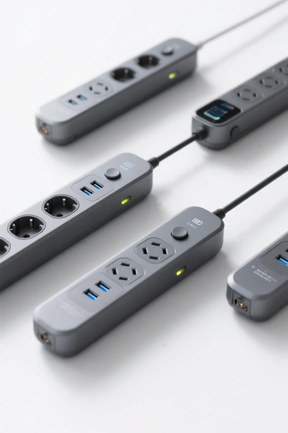
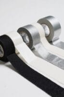
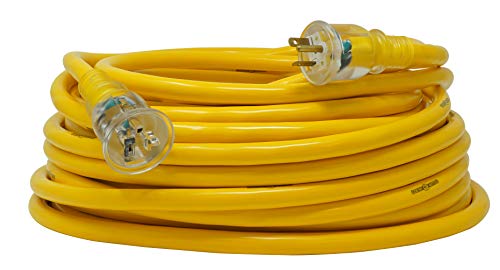
Recoil Extension Cords: Design Milestones and User Benefits
When installed correctly, recoil extension cord model RC-500 retracts to 1.2 m and extends to 7.6 m for typical jobsite use. The article traces recoil extension cords from 1950s spring-loaded reels to modern, Wi-Fi enabled reels. In the 1950s springs allowed automatic retraction; in the 1970s cord-locks secured length at points; in the 1990s reinforced sheaths and integrated circuit breakers improved performance. Present models use advanced polymers for lighter reels and improved usability, and some offer remote monitoring. Users can extend to specified 7.6 m, lock at measured intervals, and retract to 1.2 m for storage. Designers now emphasize energy efficiency and plan sustainable materials and renewable integration. Model codes, length specs, and basic operation steps are provided. Refer to RC-500 manual for specifics. Many modern models feature SJTW jackets for enhanced weather resistance.

Jobsite Power Distribution: The Southwire Temporary Power Cable splits 50-amp service with a distribution extension cord design, offering rugged, flexible, oil-resistant performance

Heavy-Duty Generator Connection: The Southwire Cord is a generator extension cord and rugged cord with Hubbell ends for reliable power in tough environments.
DURABLE 10 gauge; 3 PRONG L520 TBLADE; 100 ft extension cord
Safety and Durability Improvements in Field Tools
A common upgrade replaced wooden poles with fiberglass poles such as model FG-240, rated 2.4 m and 10 kV insulation. The change delivered Improved Safety by reducing conductive risks near live conductors. Crews then used bucket trucks with hydraulic lifts rated 3,000 kg, minimizing pole climbing. Inspection steps followed: first inspect FG-240 for cracks and confirm 2.4 m length; second test hydraulic lift travel and 3,000 kg load limit; third verify rubber gloves size 11, sleeve dielectric 20 kV; fourth confirm hot stick length 3.6 m and ASTM compliance. Finally issue advanced PPE, including ergonomic harnesses and arc-rated clothing. These measures extended tool life and lowered incident rates during maintenance. Record each inspection date, serial number, and corrective action in the equipment logbook monthly. Many cable wraps use PET braided sleeving for heat resistance and durability.

Extension Poles Kit includes: (3) 6' extension poles (FG-6), (1) 3' extension pole (FG-3)

Includes (2) 6-foot extension poles, (1) 6-foot base pole, & (1) 3-foot extension pole

Extends to 18-feet in 10 seconds
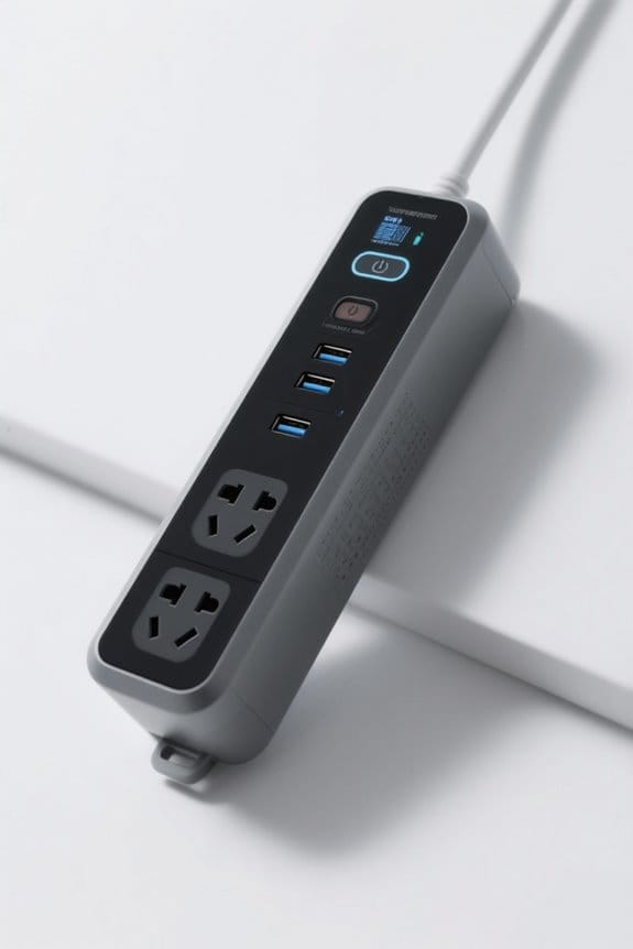
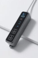
The Impact of Smart Grid Technologies on Extension Items
Following the FG-240 upgrade, smart grid features further improved extension item management across field operations and inspection routines. Smart grid technologies enable real-time tracking of power at 1 kW resolution, guiding deployment of extension cord reel model CR-12A. IoT sensors, type IS-07, report temperature to ±0.5°C and cable tension at 5 N accuracy for safety checks. Automatic rerouting uses 3 redundant feeds, labeled R1-R3, improving reliability during outage protocols and automatic failover verification routines. Smart meters SM-100 record voltage and run hourly logs for performance analysis and maintenance scheduling. Digitized distribution controls reduce manual cord handling by 40%, using cord management unit CMU-3 with 2.5 m cable spools. Field technicians follow steps: verify sensor ID, log readings, reset CMU, and confirm reroute each time.
Integrated Planning and Coordination Across Utility Functions
Often planners coordinate utility functions through shared data standards, ensuring 1 kW resolution load reports and synchronized hourly SM-100 meter logs. Integrated planning now requires clear steps: 1) collect 1 kW CSV output from SM-100 meters, file code EPRI-CEP-202, timestamp UTC. 2) validate CSV against IEEE 2030.5 schema, check voltage within 120±5 V. 3) import into GIS layer EPSG:4326, link poles by tag P-XXXX. 4) run load flow with 15-minute intervals, set inverter models to IEC 62116. Collaborative teams compare electric and gas maps, note interdependencies during winter storms. The guidance preserves reliability and guides hardware upgrades to accept two-way flows. Planners follow these steps to align distribution upgrades and cross-system coordination. Periodic audits use meter tag SM-100A and report ID RPT-01 monthly regularly. Additionally, using surge protectors with ETL certification and high joule ratings can help protect monitoring and control devices during transient events.
DIY Techniques and Community-Led Pole Maintenance
When a utility pole shows surface rot or leans, homeowners can follow measured DIY steps to extend service life and stabilize the structure. Property owners inspect the pole, note decay depth, and measure 18 inches below grade and 6 inches above grade. Common diy techniques begin by driving a 3 in. x 8 ft fence post 36 inches into firm soil beside the pole. Strap the post to the pole with two 3/8-inch stainless bolts and 1 in. steel straps at 24-inch centers. For encasement, split a 45-gallon barrel, place halves around the base, and fill with concrete to 12 inches depth. Metal stays bolted to a wall provide lateral support. Consider Polesaver PS-12 for long-term preservation. Residents coordinate permits and document actions regularly. For electrical work near the pole, use 10 AWG wiring for 30A connections to minimize overheating and voltage drop.

220V 50/60Hz single phase, 29A, 6400 watts (rotation speed: 400 watts)

Solar Pond Aerator (Battery-Free): Daytime solar-direct aeration—no AC wiring or batteries; ideal for ponds and small lakes.
🔥High-Powered Heating: This 2900W electric infrared heater provides instant, even heat with sophisticated infrared technology that concentrates heat onto individuals and objects. It efficiently heats up to 121 Sq Ft of area, turning your outdoor living area into a luxurious warm retreat in no time.
Independent Testing, Standards, and Regulatory Drivers
Test samples should be sent to an ISO/IEC 17025-accredited lab for independent testing, using three 12-inch core samples per pole or device. First, label each core with pole ID, date, GPS coordinates, and sample depth in inches, following form code UX-100. You can package cores in sealed poly bags, use 2-mil thickness, and include desiccant sachet item number DS-24, label orientation, record ambient temperature and humidity. Standards to check include ANSI C2, IEEE 693, and OSHA 1910 sections relevant to live-line work and fall protection. Independent testing labs report tensile strength in psi, moisture content percent, and decay rating using ASTM D4442 procedures, clause 7.2. Regulatory updates require re-testing every five years, document results in database field REF-RT-5Y, and notify OSHA if failures occur. Replacement power cords for associated equipment should be UL-certified to ensure compliance with recognized safety standards.
Future Trends: Sustainable Materials and Remote Monitoring
Because utilities increasingly adopt sustainable polymers and composites, manufacturers specify materials with measured life-cycle emissions and known mechanical ratings. Future items use sustainable materials such as PE-RT blend 1.2 g/cm3 and PLA composite 0.95 g/cm3, part code UEX-1001. Designers include IoT sensors model SNT-45 that sample at 1 Hz and report via Wi-Fi. Installers follow three steps: 1) mount device at 1.5 m height using M6 screws torque 5 N·m; 2) connect power using IEC 60320 C13 cable length 2.0 m; 3) register device to app using SSID and password. Predictive algorithms flag wear when sensor reports vibration above 2.5 g for 60 seconds. Remote monitoring lowers downtime and improves safety on job sites. Service logs export CSV files named UEX_log_YYYYMMDD.csv for analysis locally. Devices often include weatherproof surge protectors with IPX6 rating to resist rain and splashes.
Frequently Asked Questions
How Has Energy Use Changed Over Time?
Energy use has shifted from coal and oil dominance to diversified electricity, natural gas, and renewables, driven by efficiency, crises, and technology; Energy Consumption patterns now emphasize lower emissions, distributed generation, and smart-grid management strategies.
What Are Utility Extensions?
More essential than oxygen, utility extensions are devices that extend electrical power beyond fixed outlets, enabling access, enhanced safety features, cord management, and Utility upgrades for homes, workshops, and outdoor tasks, improving convenience and control.
How Did Energy Change in the System Over Time?
Energy Evolution shifted from coal dominance to natural gas and then to renewables, driven by crises, market restructuring, digitization and electrification; the system adapted via grid upgrades, two-way flows, DER integration and coordinated planning responses.
How Has the Use of Natural Gas Changed Over Time?
About 40% of U.S. electricity generation now comes from natural gas. Analysts call this Natural Gas Evolution a coal-to-gas shift enabled by fracking, lower prices, and grid flexibility supporting renewables, cutting emissions, central in planning.